Oem Pu Sandwich Panels Top Suppliers: Specification, Ordering and Quality Notes
Scope of Supply and Physical Form
Critical spec rule: Panel thickness tolerance is ±1.5 mm on the core and ±0.3 mm on each facing. Exceeding this range triggers joint misalignment on site and voids the thermal performance declaration.
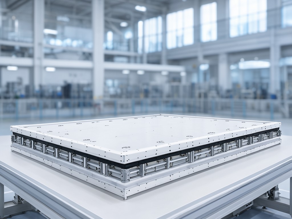
Standard supply covers thicknesses from 50 mm to 200 mm in 10 mm increments, widths of 1000 mm or 1150 mm, and lengths up to 12 m ex‑factory. Facings are pre‑painted galvanized steel (0.4–0.7 mm) or stucco‑embossed aluminum (0.5–0.8 mm). Core density is fixed at 40 kg/m³ ±2 kg/m³ for the standard PU formulation; higher densities are a custom line item.
Each bundle is strapped with PET banding, edge‑protected with cardboard corners, and wrapped in UV‑stabilised polyethylene film. Bundle weight is capped at 2.5 t to suit standard container loading. Batch traceability labels include production date, foam lot number, and facing coil ID.
Materials and Construction Trade-offs
The facing metal dictates both corrosion life and thermal bridging. Galvanized steel with a 25 µm polyester topcoat delivers 15–20 years in C3 environments; upgrading to a 35 µm PVDF system pushes that to 25+ years but adds 8–10% to panel cost. Aluminum facings eliminate red‑rust risk entirely and reduce dead load by ~1.2 kg/m², yet their higher thermal conductivity increases the effective U‑value by 0.02–0.03 W/m²K.
Core blowing agent choice affects long‑term lambda stability. Cyclopentane‑based foam retains 95% of its initial λ (0.022 W/mK) after 10 years; cheaper HCFC‑141b blends can drift to 0.028 W/mK within five years in warm climates. The adhesion line uses a two‑component polyurethane adhesive applied at 180–220 g/m²; under‑application causes delamination at the tongue‑and‑groove joint under thermal cycling, while over‑application creates brittle bond lines that crack during transport.
Comparing Two Standard Configurations
Config A — Steel / 40 kg/m³ PU / Polyester 25 µm
- U‑value 0.22 W/m²K at 100 mm
- Weight 11.8 kg/m²
- Fire rating B‑s2,d0 (EN 13501‑1)
- Typical lead time 3 weeks
Config B — Aluminum / 42 kg/m³ PU / PVDF 35 µm
- U‑value 0.24 W/m²K at 100 mm
- Weight 10.6 kg/m²
- Fire rating B‑s1,d0 (EN 13501‑1)
- Typical lead time 4 weeks
Config A is the workhorse for cold‑store walls where fire rating B‑s2,d0 meets local code and the slight thermal advantage matters. Config B wins on coastal projects where salt spray cycles would degrade steel within the warranty period; the lighter weight also reduces sub‑structure cost on long‑span roofs.
What Can Be Customised and What Cannot
Customisable
- Facing colour (RAL or corporate match)
- Core density 38–45 kg/m³
- Length per panel (up to 16 m with jointed transport)
- Factory‑applied vapor barrier foil
Fixed
- Tongue‑and‑groove profile geometry
- Foam blowing agent (cyclopentane only)
- Adhesive chemistry (two‑component PU)
- Maximum bundle width for containerisation
Colour matching requires a signed-off physical swatch; digital proofs are not accepted because polyester and PVDF cure differently under the line’s IR ovens. Core density changes alter the press cycle time and therefore the per‑square‑metre cost — expect a 3–5% price shift per 2 kg/m³ step.
Inspection Items and Test Methods
Every production lot undergoes density verification (ASTM D1622) on three core samples per 500 m², adhesion peel test (EN 14509 Annex C) on two joints per 1000 m², and dimensional check on 100% of panels for thickness, width, and squareness. Thermal conductivity is sampled quarterly via guarded hot plate (ISO 8301) on retained foam blocks. Fire classification is maintained by annual witness testing at a notified body; the certificate covers the standard facing/foam combination only.
Salt‑spray exposure (ISO 9227, 500 h) is run on each new facing coil batch. Colour fastness (ISO 105‑B02) is verified on the first panel of every colour run. Non‑conforming panels are segregated, re‑worked if the defect is adhesive‑only, or scrapped if foam delamination exceeds 5% of the bond area.
Keeping Repeat Orders Supplied
| Configuration | Typical MOQ (m²) | Lead Time (weeks) | Tooling Required |
|---|---|---|---|
| Config A (standard colour) | 500 | 3 | None |
| Config A (custom colour) | 1000 | 4 | Coil changeover |
| Config B (standard colour) | 800 | 4 | None |
| Config B (custom colour) | 1200 | 5 | Coil changeover |
| Non‑standard density | 1500 | 5–6 | Press recipe setup |
Blanket orders with scheduled releases lock in the above lead times and protect against raw‑material surcharges. A 12‑month forecast allows the mill to reserve coil allocation and foam lot continuity, eliminating the colour‑drift risk that appears when separate lots are spliced mid‑project.
Setup, Use and Replacement Parts
Panels are installed with self‑drilling screws (4.8 × 35 mm for steel, 5.5 × 40 mm for aluminum) at 300 mm centres on the tongue side. Sealant bead (neutral‑cure silicone, 6 mm diameter) is applied in the groove before engagement. Joint tape (butyl‑backed, 50 mm wide) covers the exterior seam; it must be replaced if the panel is removed because the butyl loses tack after one thermal cycle.
Replacement facings are stocked in 1 m² cut‑to‑size sheets for the top‑five RAL colours; lead time is 5 working days. Full‑panel replacement requires the original production lot number to match foam batch and facing coil. Warranty covers delamination exceeding 10% of bond area within 10 years, provided installation records show correct screw torque (2.5 Nm ±0.3 Nm) and sealant application.
Request a Tooling Review
Submit your project schedule and panel specification for a no‑obligation tooling and capacity assessment. We’ll confirm MOQ, lead time, and the exact coil allocation needed to hold your colour consistency.
Start the review →